As a supplier of Q235B Black Welded Pipe, I often receive inquiries from customers about how to calculate the flow capacity of these pipes. Understanding the flow capacity is crucial for various applications, including water supply systems, industrial fluid transportation, and HVAC systems. In this blog post, I will provide a detailed guide on how to calculate the flow capacity of Q235B Black Welded Pipe.
Understanding Q235B Black Welded Pipe
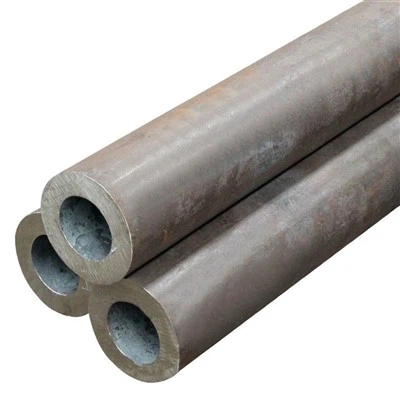
Q235B Black Welded Pipe is a type of carbon steel pipe that is widely used in various industries due to its excellent mechanical properties and affordability. The "Q235B" designation refers to the steel grade, which indicates a minimum yield strength of 235 MPa. The black color comes from the presence of a thin layer of iron oxide on the surface of the pipe, which provides some protection against corrosion.
These pipes are typically manufactured using the electric resistance welding (ERW) process, which involves heating the edges of the steel strip and then pressing them together to form a continuous weld. The resulting pipe has a smooth interior surface, which is ideal for fluid flow applications.
Factors Affecting Flow Capacity
The flow capacity of a pipe is determined by several factors, including:
- Pipe Diameter: The larger the diameter of the pipe, the greater the flow capacity. This is because a larger diameter provides more cross-sectional area for the fluid to flow through.
- Pipe Length: The longer the pipe, the greater the frictional resistance to flow. This means that the flow capacity will decrease as the length of the pipe increases.
- Fluid Viscosity: The viscosity of the fluid affects its ability to flow through the pipe. More viscous fluids, such as oil, will have a lower flow capacity than less viscous fluids, such as water.
- Fluid Velocity: The velocity of the fluid also affects the flow capacity. Higher velocities can increase the flow rate, but they also increase the frictional resistance and the likelihood of turbulence.
- Pipe Roughness: The roughness of the interior surface of the pipe can affect the flow capacity. A smoother surface will have less frictional resistance and a higher flow capacity than a rougher surface.
Calculating Flow Capacity
There are several methods for calculating the flow capacity of a pipe, but the most commonly used method is the Darcy-Weisbach equation. This equation relates the head loss due to friction in a pipe to the flow rate, pipe diameter, pipe length, fluid viscosity, and pipe roughness.
The Darcy-Weisbach equation is given by:
[
h_f = f \frac{L}{D} \frac{V^2}{2g}
]
where:
- (h_f) is the head loss due to friction (in meters)
- (f) is the Darcy friction factor
- (L) is the length of the pipe (in meters)
- (D) is the diameter of the pipe (in meters)
- (V) is the average velocity of the fluid (in meters per second)
- (g) is the acceleration due to gravity (9.81 m/s²)
The Darcy friction factor (f) depends on the Reynolds number (Re) and the relative roughness (\epsilon/D) of the pipe. The Reynolds number is a dimensionless number that represents the ratio of inertial forces to viscous forces in the fluid flow. It is given by:
[
Re = \frac{\rho V D}{\mu}
]
where:


- (\rho) is the density of the fluid (in kg/m³)
- (\mu) is the dynamic viscosity of the fluid (in Pa·s)
The relative roughness (\epsilon/D) is the ratio of the roughness height (\epsilon) of the pipe interior surface to the pipe diameter (D). For Q235B Black Welded Pipe, the roughness height can be estimated to be around 0.046 mm.
Once the Reynolds number and the relative roughness are known, the Darcy friction factor (f) can be determined using the Moody chart or the Colebrook equation. The Colebrook equation is an implicit equation that relates the Darcy friction factor to the Reynolds number and the relative roughness:
[
\frac{1}{\sqrt{f}} = -2.0 \log_{10} \left( \frac{\epsilon/D}{3.7} + \frac{2.51}{Re \sqrt{f}} \right)
]
This equation can be solved iteratively using a numerical method, such as the Newton-Raphson method, to find the value of (f).
Once the Darcy friction factor (f) is known, the flow rate (Q) can be calculated using the following equation:
[
Q = A V
]
where:
- (A) is the cross-sectional area of the pipe (in m²)
- (V) is the average velocity of the fluid (in m/s)
The cross-sectional area (A) of a circular pipe is given by:
[
A = \frac{\pi D^2}{4}
]
Example Calculation
Let's consider an example of calculating the flow capacity of a Q235B Black Welded Pipe with a diameter of 100 mm (0.1 m) and a length of 100 m. The fluid is water at a temperature of 20°C, which has a density of 998 kg/m³ and a dynamic viscosity of 0.001 Pa·s. The pressure drop along the pipe is 10 kPa.
First, we need to calculate the Reynolds number:
[
Re = \frac{\rho V D}{\mu}
]
We can assume an initial value of the velocity (V) and then iterate to find the correct value. Let's assume an initial velocity of 1 m/s.
[
Re = \frac{998 \times 1 \times 0.1}{0.001} = 99800
]
Next, we need to calculate the relative roughness:
[
\epsilon/D = \frac{0.000046}{0.1} = 0.00046
]
Using the Colebrook equation, we can solve for the Darcy friction factor (f):
[
\frac{1}{\sqrt{f}} = -2.0 \log_{10} \left( \frac{0.00046}{3.7} + \frac{2.51}{99800 \sqrt{f}} \right)
]
Using a numerical solver, we find that (f = 0.019).
Now, we can use the Darcy-Weisbach equation to calculate the head loss:
[
h_f = f \frac{L}{D} \frac{V^2}{2g}
]
[
10000 = 0.019 \frac{100}{0.1} \frac{V^2}{2 \times 9.81}
]
Solving for (V), we find that (V = 1.02) m/s.
Finally, we can calculate the flow rate:
[
Q = A V = \frac{\pi D^2}{4} V = \frac{\pi \times 0.1^2}{4} \times 1.02 = 0.008 m^3/s = 8 L/s
]
Conclusion
Calculating the flow capacity of Q235B Black Welded Pipe is an important step in designing fluid flow systems. By understanding the factors that affect flow capacity and using the appropriate equations, you can ensure that your system operates efficiently and effectively.
As a supplier of Q235B Black Welded Pipe, we offer a wide range of pipe sizes and wall thicknesses to meet your specific requirements. Our pipes are manufactured to the highest quality standards and are suitable for a variety of applications, including water supply, irrigation, and industrial fluid transportation.
If you have any questions about calculating the flow capacity of our pipes or if you would like to discuss your specific requirements, please feel free to contact us. We are here to help you find the right solution for your project.
References
- Crane, D. S. (1988). Flow of Fluids Through Valves, Fittings, and Pipe. Technical Paper No. 410M. Crane Co.
- Moody, L. F. (1944). Friction factors for pipe flow. Transactions of the ASME, 66(8), 671-684.
- Streeter, V. L., & Wylie, E. B. (1985). Fluid Mechanics. McGraw-Hill.