Electric Resistance Welded pipes are widely used in construction, oil and gas transportation, mechanical engineering, and water systems due to their dimensional accuracy and production efficiency. While material grade determines strength and chemical performance, dimensional parameters such as outside diameter, wall thickness, and schedule classification define pressure capacity, flow characteristics, and structural compatibility. Understanding the standard dimensions and size ranges of ERW pipes is essential for engineers, procurement specialists, and project designers.
Dimensional standards ensure interchangeability across global markets. ERW pipes are typically manufactured in accordance with systems such as ASME B36.10M, ASME B36.19M, API standards, and ASTM specifications. These standards regulate nominal pipe size, outside diameter tolerance, wall thickness series, and weight per unit length.
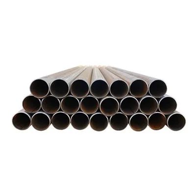
Outside Diameter Range of ERW Pipes
Nominal Pipe Size and Actual Outside Diameter
In piping systems, Nominal Pipe Size (NPS) is a standardized designation rather than a direct measurement of internal diameter. For smaller sizes, the outside diameter remains constant while wall thickness changes according to schedule classification. For larger diameters, the outside diameter increases directly with nominal size.
ERW pipes are commonly produced from small diameters used in mechanical systems to large diameters suitable for transmission pipelines. Typical outside diameter ranges extend from approximately 1/2 inch (21.3 mm) up to 24 inches (610 mm) or even larger depending on mill capability.
Smaller ERW pipes are often applied in building services and structural frameworks, while medium and large diameters are widely used in fluid transmission and energy pipelines.
Dimensional Tolerances
Dimensional precision is a defining advantage of ERW manufacturing. Outside diameter tolerance, wall thickness variation, and straightness are strictly controlled during forming and welding. Tight tolerances ensure compatibility with fittings, flanges, and threaded or welded connections.
The following table summarizes common nominal sizes and corresponding outside diameters according to widely adopted standards.
| Nominal Pipe Size (NPS) | Outside Diameter (mm) | Typical Application Field | Dimensional System |
|---|---|---|---|
| 1/2" | 21.3 | Plumbing & light mechanical | ASME B36.10M |
| 1" | 33.4 | General fluid systems | ASME B36.10M |
| 2" | 60.3 | Industrial piping | ASME B36.10M |
| 4" | 114.3 | Process pipelines | ASME/API |
| 8" | 219.1 | Oil & gas transport | API 5L |
| 12" | 323.9 | Water transmission | API/ASTM |
| 16" | 406.4 | Energy infrastructure | API |
| 24" | 609.6 | Large-scale pipeline | API |
This dimensional system ensures global uniformity in pipe sizing and fitting compatibility.
Wall Thickness Series and Schedule Classification
Schedule (Sch) System
Wall thickness is categorized under the Schedule (Sch) system. The schedule number indicates relative wall thickness, with higher schedule numbers corresponding to thicker walls and greater pressure capacity. Common schedules include Sch 10, Sch 20, Sch 40, Sch 80, Sch 160, and XS (Extra Strong).
For a given nominal pipe size, increasing the schedule increases wall thickness while keeping the outside diameter constant. This design approach allows engineers to select appropriate pressure ratings without altering connection dimensions.
For example, a 4-inch pipe in Sch 40 has a thinner wall than a 4-inch pipe in Sch 80, even though both share the same outside diameter of 114.3 mm.
Wall Thickness Range
ERW pipe wall thickness typically ranges from about 1.5 mm for light mechanical tubing to over 25 mm for heavy-duty pipeline applications. Thicker walls enhance burst resistance and structural strength but increase weight and cost.
The following table illustrates representative wall thickness values for selected nominal sizes and schedules.
| NPS | Schedule | Wall Thickness (mm) | Approximate Weight (kg/m) | Typical Pressure Use |
|---|---|---|---|---|
| 2" | Sch 40 | 3.91 | 5.44 | Medium-pressure service |
| 2" | Sch 80 | 5.54 | 7.48 | Higher-pressure systems |
| 4" | Sch 40 | 6.02 | 16.07 | Process piping |
| 4" | Sch 80 | 8.56 | 22.32 | Industrial high pressure |
| 8" | Sch 40 | 8.18 | 42.55 | Oil & gas pipelines |
| 8" | Sch 80 | 12.70 | 63.78 | Heavy-duty transmission |
This schedule-based system provides flexibility in design without altering overall piping layout.
Weight Calculation Method
Formula for Theoretical Weight
The theoretical weight of ERW pipe can be calculated using a geometric formula based on outside diameter and wall thickness. In metric units, the simplified formula is:
Weight (kg/m) = 0.02466 × (OD − t) × t
Where OD represents outside diameter in millimeters and t represents wall thickness in millimeters. This formula assumes carbon steel density of approximately 7.85 g/cm³.
Accurate weight calculation is essential for structural load analysis, transportation planning, and cost estimation. Heavier pipes require stronger supports and increase installation complexity.
Practical Implications of Weight Variation
As schedule increases, weight rises proportionally. While thicker pipes provide greater pressure resistance, they also increase material consumption and project expense. Engineers must balance safety requirements with economic considerations when selecting wall thickness.


Common Standard Size Systems
ASME and ASTM Systems
ASME B36.10M governs carbon steel pipe dimensions, while ASME B36.19M applies to stainless steel. These standards define nominal size, outside diameter, and schedule series. ASTM specifications reference these dimensional systems while specifying material properties.
API System for Line Pipe
For pipeline applications, API 5L standardizes dimensional parameters and tolerances. Large-diameter ERW pipes used in oil and gas transmission commonly follow API dimensional guidelines, including strict control of roundness and wall thickness uniformity.
Global standardization ensures that ERW pipes manufactured in different regions remain compatible with fittings, valves, and engineering designs worldwide.
Relationship Between Dimensions and Performance
Outside diameter influences flow capacity and structural rigidity. Wall thickness determines internal pressure resistance and collapse strength. Schedule classification provides a systematic method to match pipe strength to operating conditions. Weight affects installation, support design, and overall project economics.
Dimensional selection is therefore a multidisciplinary decision involving mechanical engineering, fluid dynamics, and cost optimization.
Conclusion
Standard dimensions and size ranges of ERW pipes are defined through internationally recognized systems that regulate outside diameter, wall thickness, schedule classification, and weight calculation. ERW pipes typically range from small diameters used in building services to large diameters applied in energy transmission. The schedule system allows flexible strength selection without altering external dimensions, while weight calculations support structural and logistical planning. By understanding these dimensional parameters and standard size frameworks, engineers can design safe, efficient, and cost-effective piping systems for a wide range of industrial applications.